Quantcast
Channel: Bentley Communities
Viewing all 4537 articles
Browse latest View live

Updated patch sets now available for Water and Storm & Sewer products

$
0
0

The most current patch sets for the products listed below are now available to download from the "SELECT Released Products" section of SELECT Downloads webpage. Note that these patch sets must be installed after the full installation of the referenced product version (i.e., software download from "SELECT Released Products" section), and they cannot be used with any version other than that specified.

• Bentley WaterGEMS V8i - Cumulative Patch Set for build 08.11.04.50 and build 08.11.04.57, posted 8/15/13
• Bentley WaterCAD V8i - Cumulative Patch Set for build 08.11.04.50 and build 08.11.04.57, posted 8/15/13
• Bentley HAMMER V8i - Cumulative Patch Set for build 08.11.004.50 and build 08.11.04.57, posted 8/15/13
• Bentley StormCAD V8i - Cumulative Patch Set for build 08.11.03.77 and build 08.11.03.83, posted 8/15/13
• Bentley StormCAD V8i United Kingdom - Cumulative Patch Set for build 08.11.03.77 and build 08.11.03.83, posted 8/15/13
• Bentley SewerGEMS V8i - Cumulative Patch Set for build 08.11.03.77 and build 08.11.03.83, posted 8/15/13
• Bentley SewerCAD V8i - Cumulative Patch Set for build 08.11.03.77 and build 08.11.03.83, posted 8/15/13
• Bentley CivilStorm V8i - Cumulative Patch Set for build 08.11.03.77 and build 08.11.03.83, posted 8/15/13

There is a slight change to the process of downloading our patch sets. In the search screen, instead of choosing “Enhancements and Updates”, leave the Download Category as “SELECT Released Products”. Make sure the check box is checked for showing dependencies. In the search result, the patch will then show as a dependency of the main product. Note that the patch sets for WaterGEMS and SewerGEMS will be available to download from the "Enhancements and Updates" section as before.

Refer to the following wiki solution for more details: http://communities.bentley.com/products/hydraulics___hydrology/w/hydraulics_and_hydrology__wiki/how-to-download-watergems-watercad-hammer-sewergems-sewercad-civilstorm-stormcad-pondpack-flowmaster-culvertmaster.aspx

Other items of note:

• All patch sets are cumulative; that is, they contain all available updates for the specific product and version up to the time of posting. You need only install the latest patch set to become current. 
• The software product must be closed prior to installing the update.
• Patch sets are refreshed on SELECTservices Downloads on a monthly basis.
• For further assistance with software updates and patches, please contact technical support at http://www.bentley.com/serviceticketmanager.

Note that these patch sets must only be installed on a machine where you have the specific product version listed above already installed. They are not compatible with any other version. To check what version you have installed, open the product, go to Help > About. The build number will be in the lower left corner of the dialog in brackets.


New Course! Learn SACS Model Building Fundamentals

$
0
0

For the first time, Bentley Institute is offering a live training course about SACS offshore modeling fundamentals. Learn the basics to become proficient in analyzing and designing offshore structural models to improve infrastructure operational safety and minimize risk.

Held in the virtual classroom August 28 - 29, 2013 from 8:30 am – 12:30 pm CDT, Jacket Type Structure Modeling Fundamentals teaches you the skills required to perform a static linear analysis using Bentley’s offshore analysis and design software. You will learn how to:

  • Define jacket and jacket piles
  • Guide framing and diagonal members
  • Create a deck
  • Define the loading of structures

Join the class right from your own computer to interact with an expert instructor, perform hands-on exercises, and accrue Learning Units – Bentley’s equivalent to professional development hours – to maintain your credentials.

Don’t miss the chance to gain new SACS skills to become more efficient and effective on the job. For more details or to register now, see the course description.

Beta Testers Needed for RAM Structural System V8i Release 14.06

$
0
0

RAM Structural System Users:

RAM Structural System V8i Release 14.06 is scheduled to be released early Q4, 2013. It includes several significant enhancements and changes, including a 64bit version that provides for larger models at better performance, and new licensing scheme conforming to Bentley’s Trust Licensing. A list of significant enhancements can be found at:

http://communities.bentley.com/products/structural/structural_analysis___design/b/analysis_and_design_blog/archive/2013/08/13/ram-structural-system-v8i-release-14-06-new-features-and-enhancements.aspx

Before releasing this version we would like to have the Beta version of the program tested by engineering firms, with real models under real conditions. This is very beneficial to us as it helps us find and resolve problems before the commercial release. Internally we perform extensive testing, but Beta testing is valuable because it helps identify problems in models unlike any of our test models, or in the way commands are used in conjunction with other commands, or on computer systems with configurations that are different than our own.

To be of value, Beta testing takes time and effort. You are likely to encounter problems and errors, which then take time to document and work with us to resolve. You should be suspicious of any results produced by the Beta, as we are still in the process of performing QA, and expect that changes and corrections will be required.

Models created in previous versions are compatible with V14.06, but models created in or Saved in V14.06 are not backward compatible with previous versions. It is recommended that before opening an existing model in the Beta version that a copy be made so that you can continue to work on that model in the previous version.

Two versions of the program cannot be installed simultaneously on one computer. However, you can install the V14.06 Beta over previous versions, and you can uninstall V14.06 and reinstall the previous version to return to working with that. When this is done, databases are preserved, they are not deleted by the uninstalling of the Beta.

We would appreciate anyone interested in helping with the Beta testing. If you are interested, please contact me at: allen.adams@bentley.com. Please put “Beta” in the subject line.

Thanks.

Allen Adams, P.E., S.E.

Chief Structural Engineer

Product Manager, RAM Structural System


Request update license

Point Cloud data import

$
0
0

Following are the steps to import the point cloud data
to create survey model in MXRoad

1. From the CAD menu go to "File > Point Clouds" to bring up the panel below :


2. Select "File > Attach" and then browse to the folder containing the point cloud data. Say, *.xyz format. Hit 'Open' to open the 'Convert Generic Text' dialog box. Here, you can change the settings for the import. Hit OK to continue and the POD file, this is a part of the conversion process and the file is attached to the drawing similar to a reference file. Fit View will show the imported clouds.

3. Now, go to "Tools > Data Acquisition", right click on 'Surface', select 'Create Surface > Import From Point Clouds'.

The 'Point Cloud Surface' panel will appear, select 'No Filter' and Accept.

The point clouds will now be imported as surface. You can detach the point cloud pod file now, as it has been imported into the Data Acquisition.

4. MX will not import if the naming contains certain characters, i.e. _ / etc. At this stage it is best to rename the point cloud surface to a name you will use in MX, for example DTM Survey. You can change this in the Data Acquisition Details panel as shown below:

5. Now, right on the DTM survey in the 'Data Acquisition' panel and select 'Export > MX modelfile'.

Select the model.fil for the project and select Save.

6. In the model drop down list there will now be a DTM Survey triangulation model.

Hope this article helps you to import the point cloud data and then create a survey model in MXRoad.

Tip No.7: Automatically use bolting line on Endplate connection.

$
0
0

When using the Endplate connection,


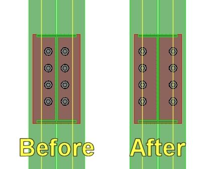
if one of the steel elements is being connected to its flange (like the column in the example below).


it is possible to have the bolt line values (defined in the shape's database) used automatically to place the bolts.

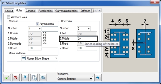
Simply enter the letter "w" in the "Middle" field of horizontal distribution and ProSteel will automatically read the value from the database and place it in the field.


how to copy element(s) (from reference or active model) to active level and zero movement

$
0
0

How to copy element(s) (from reference or active model) to active level and zero movement


Keyin: lv=al not working in V8i


LARS Bridge Version 6.00.00.00 Release Notes

$
0
0

LARS Bridge Release 6.00.00.00

Release Notes


LARS V6.00.00.00 is primarily a maintenance release with no significant functional enhancements.  It does represent the initial consolidated release where LARS Bridge is now a single product and all modules that were previously licensed separately are included in the single product.  The modules that are now part of LARS Bridge along with the core LARS Bridge modeling and load rating engine are:


  • Connector – extracts bridge models from AADHTO Bridge Rating BrR
  • Manager – Manages LARS Bridge models
  • RouteRunner – Perform batch processing and permit analysis using LARS Bridge models
  • Complex Truss – Model and load rate truss bridges with complex geometry bridges


The following are part of LARS Bridge Release 6.00.00.00:


  1. LARS Bridge single consolidated product.  Contains LARS Bridge, Connector, Manager, RouteRunner and Complex Truss.  LARS Bridge is still licensed on an annual subscription basis.
  2. An all new installer – LARS products have migrated from using InstallShield installation tool to WiX installations.  With this change, a clean install will need to be performed.  The following steps are recommended:
    1. Back-up the current “C:\BKey” folder tree to preserve any customization, data, trucks files.
    2. Uninstall existing LARS products using Control Panel àPrograms and Features
    3. Install LARS Bridge 6.00.00.00 by launching LarsBridgeEnterprise.msi.  Respond to the following prompts.
      1. Accept the license agreement
      2. Choose the installation option – Typical installs LARS Bridge only under the c\Bkey folder tree; Custom allows selection of the LARS application to be installed and where.  The individual applications are LARS Bridge, Connector, Manager, RouteRunner and Complex Truss; Complete allows installation of al LARS applications under the default c:\bkey folder tree
      3. After the install is complete LARS will be added to the Start menu as shown below.  All user documentation is also installed and available from the Start Menu.  The LARS Bridge User Manual has been updated to include access to individual chapters via links the Table of Contents,  


Several updates plus an Appendix that provides links to useful information that is posted on the LARS Wiki site.


  1. RSS Feeds – LARS Bridge 6.00.00.00 will employ RSS feeds for news relative to LARS
  2. For Steel members LARS now allows a minimum and maximum stiffener spacing within bracing panels on the Lateral Bracing & Stiffener Spacing Dialog.  This feature was added primarily for LARS users who also use the AASHTO Bridge Rating (BrR) software.  Bridges extracted from BrR using the LARS Connector previously would have only the maximum stiffener spacing in a panel.  Now the LARS Connector will pick up a minimum stiffener spacing at panels adjacent to the end and intermediate supports, which should prevent artificially low shear ratings at these locations.


  1. Miscellaneous maintenance fixes:
    1. Resolve shear rating issue with reinforced concrete members
    2. Other minor maintenance fixes
    3. Compiler upgrades


The Whisky Shop expands into Manchester

$
0
0
The Whisky Shop is taking on Selfridges and Harvey Nichols by opening its newest outlet in the heart of Manchester’s retail area.

The 600 sq ft store is spread over two floors at 3 Exchange Street, louboutin outlet, just down the road from its fellow luxury retailers.

Managing director Andrew Torrance said: “These are very exciting times for The Whisky Shop. Manchester has a fantastic retail offering
 and we’re delighted to be opening our newest store in this vibrant and interesting city.”

Slate and timber floors, glass displays and a glass shop front featuring a copper sign are designed to give the store a “comfortable
 but luxurious feel”.

The Whisky Shop’s partners Diageo and Brown-Forman will be given “prominent space”, but the store also promises to “provide
 a dedicated platform for some of the world’s most exclusive whiskies”.

A few steps from the main retail area lies The Whisky Shop Library, which features an array of rare whiskies.

“Our aim is to inform and entertain our customers,” said Torrance. “Whisky is a wonderful and diverse drink that should be enjoyed
 rather than revered.  We look forward to bringing The Whisky Shop experience to Manchester.”

Paul Simpson, managing director of Visit Manchester, added: “The Whisky Shop’s decision to open a store in Manchester is 
a testament to both its retail and its food and drink offering. We are certain the brand will experience great success in the already
 thriving area in and around Exchange Street.”

The Whisky Shop’s flagship store in London’s Piccadilly, opened in November 2012, beat Burberry’s new global flagship store 
and the bespoke Christian Louboutin outlet boutique in Selfridges to win the 2013 National Association of Design Partnership Award 
for Retail. The firm said its “commitment to design excellence is set to continue in its now has 22 stores nationwide. 

SS5 - Workframe using ALT Key-In

$
0
0

Adding Gridlines:


Setting up a large workframe can be cumbersome if many different bay sizes are required. Here's a quick way to go in and add in bay sizes that may save you some time and frustration.


To use the key-in method, Uncheck the evenly spaced option and open the dropdown box on the right.


With the dropdown open, hold the 'ALT' key and left click anywhere in the dropdown. This will bring up another dialog which will allow you to enter values for each line, separated by a comma.


The way this dialog window works is that each value entered represents one of the lines in the dropdown box. So the first value would be the first line of the dropdown, the second value would be the second line and so on in order.


If a series of equally spaced bays occur it is possible to type it in like this "4*10:0" without quotes. This will tell the system to generate 4 bays in a row at 10 feet each. Simply use a comma before and after this statement in the same way you would if you were entering a single value.


Removing the Gridlines: 

In addition to using the dropdown like usual and typing in a 0:0 value where needed, this method can also be used to reset the lines to 0:0 if needed. To remove all the bays simply open the alternate key-in dialog and type in a number greater than the amount of bays that exist times 0:0.  For example, if you had 49 bays you could open the Key-in dialog and type "50*0:0" and this would reset all the values to '0' and the bays would disappear.

 Keep in mind however that using this method will always start from the first value in the list and so if only specific values in the middle of the list should be removed then it might be easier to do it from the dropdown; unless all the values still appear in the key-in dialog when reopened, in wich case you could simply exchange the value listed with a 0.

Bentley Award Presentation at Indian Institute of Technology Madras, Chennai, India

$
0
0

13th Aug, 2013: The stage was set to felicitate the winning team for the 2013 Scott Lofgren Student Design Awards in “Innovation in Bridge/Road Technology” category.

This day Indian Institute of Technology Madras (IITM) hosted their “Civil Engineering Association” gathering for their alumni, faculties and their students representing the Civil Engineering Department. The Auditorium was full with about 300 spectators representing their Civil Engineering community.


Bentley Award Ceremony being participated IITM - Civil Engineering Association

The event began with an introduction about the gathering and welcoming guests from Bentley Systems, Incorporated. Dr. S.R. Gandhi, Head of Civil Department welcomed Bentley and shared about Bentley-IITM collaboration since past 6 years.


On Stage: (sitting L to R) Dr. S.R. Gandhi; Dr. V.R. Raju (IITM Alumni); Mohit Bradoo & Atanu Patanayak

Following was an interesting presentation by Atanu Pattanayak, Territory Executive, South Asia, Bentley Systems, Incorporated highlighting an Infrastructure project with an Engineer’s involvement in various solutions of a project. This was really inspiring for students.


Atanu motivating the Civil Engineering Students

I had the opportunity to make a presentation about Be Careers Network Academic Program and announce winners for the 2013 Scott Lofgren Student Design Competition.


Presentation on Academic Program & 2013 Scott Lofgren Student Design Competition

The winning students made a presentation about their project and challenges they encountered. Their task was to improve the road and traffic situation of existing junction near Haji Ali in Mumbai (Maharashtra State), India.


Winning team (Innovation in Bridge/ Road Technology) making presentation

With an unceasing mentoring from their Transportation faculty, Dr. Murali Krishnan and mastering on Bentley MX Road and STAAD.Pro software, they finally evolved a design which consisted of improving the existing road network, building new flyovers and junctions to overcome the issues. They were able to improve the road efficiency by 114% as well as avoid multiple conflicts to improve the speed of moving vehicles.

You may read about the Student project at www.bentley.com/studentdesignwinners or view University website – http://www.civil.iitm.ac.in/node/780.

This was the moment to announce the winning team for “Innovation in Bridge/ Road Technology” category and you could hear 300 students hailing for the winning team – Siddhesh, Aakanksha & Dinesh.


 (L to R) Winning team - Dr. J. Murali Krishnan; Dinesh Soundappa; Siddhesh Godbole & Aakanksha Jadhav receiving 2013 Scott Lofgren Student Design Award from Atanu Pattanayak

It was indeed a privilege to represent Bentley and rewarding the winning students with medals, certificates, scholarship and the Trophy.


(L to R) M. Rajathurai; Atanu Pattanayak; Dinesh Soundappa; Siddhesh Godbole; Dr. S.R. Gandhi; Dr. J. Murali Krishnan; Aakanksha Jadhav; Mohit Bradoo & Arun Kumar on stage

The event ended with a Vote of thanks from Dr. Gandhi.

Connecting to ProjectWise datasources with the Field Supervisor App

$
0
0

Bentley released a new iPad App that allows you to connect to ProjectWise in the field.  The Field Supervisor App connects to multiple project data sources, including Bentley's ProjectWise system of collaboration servers and services and eB, which controls information throughout the lifecycle of change.  The Field Supervior app connects to ProjectWise datasources through the new Bentley Web Services Gateway.  Please not that this is a different service than what was used when connecting with the
ProjectWise Explorer for the iPad.  To learn more about the Field Supervisor app please visit the links below. (Please visit the site to view this media)

Product Page: http://www.bentley.com/en-US/Free+Software/Field+Supervisor.htm

Corporate Announcement: http://www.bentley.com/en-us/corporate/news/quarter+3/field+supervisor.htm

Mobile Apps: http://www.bentley.com/en-US/Free+Software/mobile+apps.htm

Vlak geometrie omzetten naar punt geometrie.

$
0
0

Tijdens het aanmaken van objecten die bijgehouden worden m.b.v. Bentley Map dient van te voren te worden welke geometrie type de objecten hebben. Punten, lijnen of vlakken. Het kan voorkomen dat objecten opgeslagen zijn als polygonen maar dat de gebruiker toch punt gegevens nodig heeft. In bijgevoegd voorbeeld heeft de gebruiker met een XFM schema Cultuur Historische gegevens getekend als een vlak. De interne klant heeft nu van de vlakken punt informatie nodig (XY gegevens).

Dit kan op verschillende manieren. In dit voorbeeld worden de gegevens m.b.v. de Bentley Map tool DGN2SDO weggeschreven naar Oracle Spatial (Locator) en views worden de XY-gegevens uit de database gehaald.

De werkwijze is als volgt.

  • Run DGN2SDO.
  • Laad de data in Oracle met SQLLOADER.
  • Creer views om punt geometrie aan te maken (Eenmalig) of creer tabel en view (na elke laad actie tabel create actie uitvoeren).
  • Run een script om de data te exporteren naar txt/csv.

Dit is een voorbeeld uit te praktijk. Een beschrijving en voorbeeld batch files zijn toegevoegd.

Heeft u nog vragen neem dan contact op met Marc.Rietman@Bentley.com

Extensions-visualisierung

$
0
0

Hallo liebe Bentley Freunde

Ich habe bei der Neuinstallation  der V8i-SS3die Erweitreungen  für die Visualisierung von Jerryflyn- 

  a Planzen von Xfrog

    sowie b +c Cars von Dosch

leider nicht mit installiert und möchte aber nicht  dieMcrostation komplett nochmals installieren!

Wer kann mir da helfen

Wo kann ich sie eventuell extra herunterladen?

Mit lieben Grüßen aus Hamburg

Detlef Spahn

Configuring Standard Settings for DWG Open and Save As DWG

$
0
0

Overview

With the standard installation of MicroStation, a user can set the DWG Open options or the Save As DWG options and they are saved on their PC in the DWGdata folder. There are times when a company would like to always use a standard set of settings for opening a DWG file or saving to a DWG file. They may also what to have some project specific setting that are different than the standard settings and may vary from project to project. This can be accomplished with the use of the configuration variable MS_DWGSYSTEMDATA. The variable also allows these company and project standard settings to be stored on a network.

Understanding how the standard installation works

MicroStation reads and writes the settings for opening a DWG file and saving to a DWG file in the DWGSettings.rsc file. This file and other DWG data files are located in the folder Prefs\dwgdata\. The variable MS_DWGDATA specifies the location of the folder that contains the DWG data files.

Configuring MicroStation to use standard DWG settings

The variable MS_DWGSYSTEMDATA is used to specify the location of your standard DWG data files that you don’t want to be changed. They can be for you company standard DWG data files (set the variable in the Standards.cfg) or for project specific DWG Data files (set the variable in the project configuration file).

Any DWG data files found in the folder pointed to by the variable MS_DWGSYSTEMDATA are read and used by MicroStation in place of the DWG data files found by the variable MS_DWGDATA. If a DWG data file is not found in the folder pointed to by MS_DWGSYSTEMDATA, then MicroStation will use the file in the folder pointed to by MS_DWGDATA.

The DWG data files found in the folder pointed to by MS_DWGSYSTEMDATA are only read by MicroStation. MicroStation does not write back to these files. That prevents users from changing the standards. When the user works with DWG files, MicroStation will read the settings from the folder pointed to by MS_DWGSYSTEMDATA. The user is still allowed to make any necessary changes but the changes are written back to the files in the folder pointed to by MS_DWGDATA. The next time the same user works with DWG files, MicroStation again reads from the files in the folder pointed to by the variable MS_DWGSYSTEMDATA. This way the standard DWG settings are always loaded but if there is a reason that a setting needs to be changed for a specific file, the user can temporarily make the setting change.

Configuring MicroStation to use company standard DWG settings

The company standard settings are generally stored on a network location that can be accessed by all users. The following steps can be used to setup and use the company’s DWG data standards.

  • Create a folder on the network to contain your DWG data files. The folder can be anything but I suggest something that you can identify what is contained in it. Example: StandardDWGData
  • In MicroStation, go through the DWG Open options and the DWG Save As options and set each setting to the value that you want to use for your company standards.
  • Copy the DWGsettings.rsc file and any other DWG data files, which are to be used as company standards, from the folder that is pointed to by the variable MS_DWGDATA and place them in the folder that you created on your network (StandardDWGData folder).
  • In your Standards.cfg file, add the variable MS_DWGSYSTEMDATA and set it equal to the path and folder containing the files on your network. Example: MS_DWGSYSTEMDATA = M:/cadstandards/ StandardDWGData/

MicroStation will now load the company standard DWG settings when a DWG file is worked on or when saving to the DWG file format.

Updating/Modifying the standard DWG settings

Updating or modifying the standard DWG settings is relatively easy since any changes to the DWG Open options and DWG Save As options are always written to the local DWG data files in the folder pointed to by the variable MS_DWGDATA.

  • In MicroStation, make the required changes to the DWG Open options and/or DWG Save As options.
  • Copy the DWGsettings.rsc file from the folder that is pointed to by the variable MS_DWGDATA and place it in the folder that you created on your network (StandardDWGData folder).

Your company standards have just been updated.

Configuring MicroStation to use project standard DWG settings

From time to time you may have projects that need to be worked on slightly different and require your DWG setting to be slightly different from the company standards that you normally use. This can be accomplished similar to setting up the company standard DWG settings only it will be project specific.

  • Create a folder on the network to contain your project specific DWG data files. The folder can be named anything but I suggest something that you can identify what project it is used on. You can also have one folder for each project that requires a different set of DWG settings. Example: Project1234DWGData
  • In MicroStation, go through the DWG Open options and the DWG Save As options and set each setting to the value that you want to use for that project’s standards.
  • Copy the DWGsettings.rsc file and any other DWG data files, which are to be used as the project standards, from the folder that is pointed to by the variable MS_DWGDATA and place them in the folder that you created on your network (Project1234DWGData folder).
  • In your project configuration file (.pcf file), add the variable MS_DWGSYSTEMDATA and set it equal to the path and folder containing the files on your network. Example: MS_DWGSYSTEMDATA = M:/cadstandards/ Project1234DWGData /

MicroStation will now load the project standard DWG settings when the project is selected in MicroStation manager and a DWG file is worked on or when saving to the DWG file format.

Summary

Setting up MicroStation to use company standard or project standard DWG settings is relatively easy using the methods described here. There are other methods and variables that can be used to accomplish similar results but this method is highly recommended. The variable MS_DWGSYSTEMDATA was created for the purpose of using standard DWG settings.


SS5 - Isolate Tool

$
0
0

The Isolate tool is a tool that quietly slipped in since the release of Select Series 5. This tool has been added to the ProStructures task area under MicroStation and on the View Tools toolbar under AutoCAD.


The purpose of this tool is to help visualize a shape, sub-group, group or assembly by presenting it in 4 different views. With this the selected object is automatically taken and shown with a Front, Top, Left and Iso view.


Lets take a look at an example of how this works. In this example we start with a simple model.


With the model showing, select the type of Isolation you want to create from the toolset.


In this case we will look at the 'Isolate group' function.


Click the button and then the member included in the group and the results will be something like this.


There is also an option to show the selection with adjacent parts, if I were to select the group option with adjacent parts then the result would be similar to this.


Trust Licensing in the RAM Structural System

$
0
0

Beginning with V14.06, the RAM Structural System will make the switch from Strict Licensing to Trust Licensing. The value, advantages and use of Trust Licensing are explained here.

Licensing Improvements

In this release of the RAM Structural System, a number of enhancements have been made relating to the way SELECT licensing works. The major change is the adoption of Trust Licensing – the same licensing used by all other Bentley products. In previous versions of the RAM Structural System, an IEG licensing service was used to check out a license when the application started up and check it back in when the program exited. This prevented users from being able to run the software if the number of concurrent users had reached the number of licenses owned. The RAM Structural System now uses the trust licensing approach that is a major benefit of your SELECT subscription agreement with Bentley.

Trust licensing allows any member of your engineering team to run the RAM Structural System at any time. This avoids any disruptions to your projects due to software licenses not being available to use. The RAM Structural System does not have to communicate with the license server to run and consequently this provides greater flexibility and greater reliability in operation. Instead of requiring the connection to the license server, the RAM Structural System now simply records usage of the application and allows you to access reports to see how licenses are being used in your team. License usage is aggregated and reported back to SELECTserver on a regular basis, at least once every thirty days.

You can review your team’s usage of the RAM Structural System via an easy to use web based interface to a range of reports. These reports are available at selectserver.bentley.com and let you see who used what software and when. This should be information that is valuable to you in ensuring that you are getting best value from your software. The designated account contact for your company will have permission to login to this server and to review these reports. This SELECTserver web portal also includes tools for managing licenses including limiting checkouts, forcing checkins of licenses if required, and controlling access to applications.

If your recorded usage shows a consistent peak usage that is greater than the number of licenses that you own, your Bentley account manager will contact you to discuss how the usage has occurred and review whether your license ownership matches your needs. Peak usage is the maximum number of licenses that are used within any 1 hour period.

If you would like more information on how SELECTserver and trust licensing work, you can visit:

http://www.bentley.com/en-US/Products/SELECT+Server/

For full technical details on SELECTserver licensing, start with the Introduction section of the following user manual:

https://selectserver.bentley.com/BSS/Admin/Help/en/index.html

 Trust Licensing Best Practices

  • Ensure that your designated contact person is able to login to selectserver.bentley.com and view reports on license usage
  • Review your license usage via the web portal every 2 weeks or so to better understand how your team uses RAM Structural System licenses.
  • Communicate with your Bentley Account Manager about your license usage, particularly if you expect your peak usage to increase above the number of licenses you own.
  • Use license check-out when you need to work off site without an internet connection. There is no need to check out licenses when working in a connected environment and doing so will record that license as being continuously in use. This may add to your peak usage level.

Trust Licensing FAQ

Which versions of the RAM Structural System use Trust Licensing?

All RAM Structural System products with a version number of v14.06 or later use Trust Licensing.

Can I use IEG licensed and Trust Licensed versions of the RAM Structural System on the same network?

Yes, you can mix and match Trust and IEG licensed versions of the RAM Structural System on the same network. Note that IEG licensed versions will effectively be checking out the product license for the entire run time of the product or if offline it will continue to run until checked back in. To check out a license for offline use with Trust licensing, refer to the License Management Instruction at:

http://communities.bentley.com/products/licensing/w/licensing__wiki/license-management-tool.aspx

If I use more licenses than I own, will I automatically get a bill from Bentley?

If your license usage reports show that your peak usage is consistently higher than the number of license that you own, your Bentley Account Manager will contact you and discuss options with you. These options may include adding more licenses, changing the mix of licenses that you own, short term leasing of licenses or changing how you use licenses.

Do I need an internet connection to use Trust Licensing?

You need an internet connection only when initially activating your license and at least once every month in order to record usage on the SELECTserver. For day to day use, a continuous internet connection is not required.

Solids Working Area (or SWA)

$
0
0

Quite a bit has been said about the subject... some of it being true, some of it not being so true. To help "clear the air" about it...

The best practice for solids modeling in MicroStation is to keep it simple. If you consider a 3D model in a V8 DGN file to be a "universe", keep your model at the center of that "universe" (i.e. TRUE 0,0,0). When you do that, your results will be predictable and precise. If you want to create a 3D solids model that will be used as part of an "assembly" with other models, then take advantage of MicroStation's global origin and reference using the Coincident World attachment method. You should definitely NOT create models that are far away from the center of the "universe" and use the global origin to try to make the model look like it is at the center of the "universe".

So remember, "Stay close to 0,0,0, my friends".

Gebruik van WMS met Authentication

$
0
0

Sommige WMS servers zijn beveilgd met een username / password.

Deze gegevens zullen dan elke keer wanneer de xwms als raster refernce gekoppeld wordt ingegeven te worden.


wanneer een dgn geopend wordt met daaraan gekoppeld de xwms dient tevens de credentials ingevuld te worden.


Het is mogelijk om de credentials in de xwms op te nemen zodat deze gegevens niet elke keer ingevuld hoeven te worden.

Werkwijze is als volgt:

  1. maak een xwms aan.
  2. open deze xwms met een xml editor (bv Notepad++)
  3. vervang de url string

<BentleyWMSFile>
<VERSION>1.3</VERSION>
         <URL>https://atlas.cyclomedia.com/geodata/WMS?</URL>
         <REQUEST>       
              <VERSION>1.1.1</VERSION>       
              <SRS>EPSG:28992</SRS>     
              <LAYERS>NL_aerial_2013_steden_10cm</LAYERS>    
             <STYLES/>    
             <FORMAT>image/png</FORMAT>    
              <TRANSPARENT>TRUE</TRANSPARENT>
         </REQUEST>

door

          <URL>https://username:password@atlas.cyclomedia.com/geodata/WMS?</URL>


Denk aan de : (dubbele punt) tussen username en password en de @(Add) achter het password.

Wanneer de xwms nu als referenced gekoppeld wordt wordt er niet gevraagd om de credentials..

Als voorwaarden geldt dat in de username en password geen bijzondere karakters zoals @, -, : voor mogen komen. U e-mail adres kan dus niet als user gebruikt worden.

 Tip. Voeg de xwms als een button toe aan een dgnlib zodat de wms simpel geladen kan worden. Zie voor een voorbeeld van zo'n dglib de PDOK WMS omgeving.

 Bij vragen neem contact op met Marc.Rietman@Bentley.com


Windows 8 Alert File x86 / Bentley ProjectWise Does Not Exist

$
0
0

Have you installed ProjectWise on a Windows 8 computer and all works fine until you open a MicroStation file?

If it fails, do you get the message Alert File [(x86)/Bentley/ProjectWise/] does not exist?

This message will sometimes indicate that the 8.3 folder name was stripped from c:\program files(x86), when MicroStation was trying to
launch from ProjectWise.

One way to test if this is what is going on is to do the following:

On Windows 8, Run the following commands:

In desktop mode, press the Windows key and R at the same time, to show the run command line.

Type in:                       
C:/PROGRA~2/Bentley/PROJEC~1/      and click OK


Normally that command would open the PW installation folder. If it does then you may have a different problem.

If it does NOT open the ProjectWise installation folder, then the problem is related to this 8.3 folder name issue.

Noe a Trouble Report. has already been filed on this.


However, to get around this you could move the ProjectWise and MicroStation installations to a different location,

such as C:\ (file:///C:/).


Viewing all 4537 articles
Browse latest View live


Latest Images